
South African Class GM 4-8-2+2-8-4
| South African Class GM 4-8-2+2-8-4 | |||||||||||||||||||||||||||||||||||||||||||||||||||||||||||||||||||||||||||||||||||||||||||||||||||||||||||||||||||||||||||||||||||||||||
|---|---|---|---|---|---|---|---|---|---|---|---|---|---|---|---|---|---|---|---|---|---|---|---|---|---|---|---|---|---|---|---|---|---|---|---|---|---|---|---|---|---|---|---|---|---|---|---|---|---|---|---|---|---|---|---|---|---|---|---|---|---|---|---|---|---|---|---|---|---|---|---|---|---|---|---|---|---|---|---|---|---|---|---|---|---|---|---|---|---|---|---|---|---|---|---|---|---|---|---|---|---|---|---|---|---|---|---|---|---|---|---|---|---|---|---|---|---|---|---|---|---|---|---|---|---|---|---|---|---|---|---|---|---|---|---|---|---|
.jpg) No. 2298 at Krugersdorp, 23 April 1970 | |||||||||||||||||||||||||||||||||||||||||||||||||||||||||||||||||||||||||||||||||||||||||||||||||||||||||||||||||||||||||||||||||||||||||
| |||||||||||||||||||||||||||||||||||||||||||||||||||||||||||||||||||||||||||||||||||||||||||||||||||||||||||||||||||||||||||||||||||||||||
| |||||||||||||||||||||||||||||||||||||||||||||||||||||||||||||||||||||||||||||||||||||||||||||||||||||||||||||||||||||||||||||||||||||||||
| |||||||||||||||||||||||||||||||||||||||||||||||||||||||||||||||||||||||||||||||||||||||||||||||||||||||||||||||||||||||||||||||||||||||||
| |||||||||||||||||||||||||||||||||||||||||||||||||||||||||||||||||||||||||||||||||||||||||||||||||||||||||||||||||||||||||||||||||||||||||
The South African Railways Class GM 4-8-2+2-8-4 of 1938 was an articulated steam locomotive.
During 1938 and 1939, the South African Railways placed sixteen Class GM Garratt articulated steam locomotives with a 4-8-2+2-8-4 Double Mountain type wheel arrangement in goods train service on the Mafeking line out of Johannesburg.[1][2][3]
Manufacturer[edit]
By 1938 the rapidly increasing traffic on the line from Johannesburg via Krugersdorp and Zeerust to Mafeking necessitated some means to increase its capacity quickly. Electrification to at least as far as Koster was proposed, but would take a considerable time to complete. This led W.A.J. Day, Chief Mechanical Engineer (CME) of the South African Railways (SAR) from 1936 to 1939, to prepare designs for a Garratt locomotive which would be equal to two Class 19D locomotives.[1][2][3][4][5][6]

The initial designs of the Class GM Garratt were rejected by the Chief Civil Engineer, however, since the weight on the leading and trailing bogies of each engine unit would exceed the acceptable limit for the 60 pounds per yard (30 kilograms per metre) rail of the Mafeking line. To overcome the axle load objections, the water capacity of the front water tank was reduced to 1,600 imperial gallons (7,270 litres) while the rear bunker was redesigned to carry no water and with a coal capacity of 10 long tons (10.2 tonnes). The meagre water supply, which would really only be sufficient for shunting purposes, would be augmented by semi-permanently coupling a purpose-built auxiliary water tender to the locomotive.[1][2][3][4][5][6]
In effect, since Garratt locomotives had hitherto been considered as tank engines because they carry all their water on board, this arrangement introduced the tank-and-tender Garratt. In all other respects, Day's design followed that of the heavy Class GL Garratt. An order for sixteen locomotives was placed with Beyer, Peacock and Company in 1938, while the sixteen Type X-17 water tenders were built in the Pietermaritzburg shops. The locomotives were delivered in 1938 and 1939, erected in the Durban shops and numbered in the range from 2291 to 2306.[1][2][6][7]
Characteristics[edit]
The locomotives were superheated, with bar frames, Walschaerts valve gear, steam-operated reversing gear and 11 inches (279 millimetres) diameter piston valves. Since the proportions of the engine units and the wheel diameters were the same as that of the Class 19D, many of their parts were made interchangeable.[1][2][3][8]
The boilers were of outstanding proportions to enable the locomotives to cope with one particular bank on the Zeerust line which required continuous steaming for 75 minutes. The boiler barrel and outer firebox shell was made of nickel steel plates while the steel inner firebox was stayed with flexible and rigid stays, the flexible stays arranged at suitable positions along the side and back plates and also along the two front rows of the firebox crown. The firebox tube plate and inner back plate were similar to those of the Class GL. The firebox was fitted with two Nicholson thermic syphons to increase water circulation and also to provide additional heating surface. In addition, two arch tubes leading from the tube plate to the back plate provided more heating surface while supporting the brick arch.[1][2][3]
Their type H.T-1 mechanical stokers were capable of delivering 15,000 pounds (6,804 kilograms) of coal per hour, which ensured a high firing rate when required. The stoker was driven by a totally enclosed double-acting two-cylinder variable-speed reversing steam engine, located on the hind pivot casting and operated from the cab. The coal bunker on the rear engine unit's frame was designed with sloping sides to allow the coal to gravitate to the mechanical stoker's conveyor screw trough, which extended the full length of the bunker.[2]
An M.L.S. multiple-valve regulator superheater header was fitted, arranged with the regulator valves located on its saturated steam side. The regulator spindle passed through the smokebox side and the operating rods were led along the left-hand side of the boiler to the cab. Steam was fed to the superheater header through a 7 inches (178 millimetres) diameter internal steam pipe from a standpipe in the shallow dome. As an experiment, two of the engines were equipped with patent steam driers, fitted in the dome.[2]
Two of the engines were equipped with live-steam injectors on the right-hand side and exhaust steam injectors on the left-hand side. On the other fourteen locomotives, the boiler was fed by two no. 13 live-steam injectors, one on each side and situated immediately in front of the firebox, mounted low enough to ensure that water could still be drained effectively from the water tender when the engine was on a 1 in 40 (2½%) gradient. The injector feed pipes led to a combined top-feed check valve, situated on the first barrel plate on the top centre-line of the boiler. Feedwater entered the boiler through a spray nozzle beneath which was a baffle tray. The boiler was completely lagged with asbestos mattresses and covered with planished steel, carried on a steel crinoline structure and secured in position by stainless steel bands.[2]
The axle boxes of the leading and trailing wheels on each engine unit were equipped with roller bearings while the solid bronze coupled wheel axle boxes were fitted with Ajax grease lubrication systems. Soft grease lubrication was used throughout for the motion gear, except the piston rods, valve spindles and main crossheads which were oil-lubricated. Two four-feed sight lubricators, arranged in the cab, supplied oil to the steam chests, cylinders and the ball joint of the main steam pipes on each engine unit.[2]
The main cradle frame was carried on adjustable pivots. The front pivot was a spherical type, located on the front engine unit's frame between the driving and trailing coupled wheels, while the rear pivot was a flat oil-bath type, located on the rear engine unit's frame over the driving wheels. Each engine unit's frames were formed of two continuous bars, 33 feet 7 inches (10,236 millimetres) long and extending from the buffer beams at the outer ends to the cross-beams over the Bissel wheels at the inner ends. The front engine unit was equipped with steam as well as vacuum brake gear, while the hind unit was equipped with steam brake gear and handbrake gear.[2]
Water tender[edit]
.jpg)
Their Type X-17 water tenders had a 6,750 imperial gallons (30,700 litres) capacity. In spite of initial criticisms and doubts, the unusual arrangement of water tenders which had earlier only been seen on the Kitson-Meyer locomotives of the Cape Government Railways and Central South African Railways in 1903 and 1904, proved to be very effective and was later repeated upon the introduction of the Classes GMA and GO Garratts. Photographs from the 1940s show the original water tenders with a traditional high turret, later modified to a low flat-topped turret with a hinged hatch and a curved handrail across the tank barrel.[1][2][3][5]
The 1,600 imperial gallons (7,270 litres) on-board water tank on the front engine unit was only used when the water tender was temporarily disconnected from the engine at running sheds, where the locomotives had to detach and run around their water tenders to change direction. While the locomotives were still shedded at Braamfontein before the new depot at Millsite in Krugersdorp was opened, their water tenders were usually only re-attached when the engines left the depot to save space.[9]
Service[edit]
South African Railways[edit]
The Class GM was placed in service on the Mafeking line out of Johannesburg which it was designed for and where they were to give more than thirty years of service. The Johannesburg-Zeerust section over a distance of 140 miles (225 kilometres) was the most difficult on the line. A considerable part of it consisted of numerous 1 in 40 (2½%) grades and curves of 500-foot radius (152-metre), since from the Reef the elevation dropped from 5,700 to 4,600 feet (1,700 to 1,400 metres) within 20 miles (32 kilometres), followed by a rise to over 5,000 feet (1,500 metres) in the next 11 miles (18 kilometres) and then another drop to 3,585 feet (1,093 metres).[2][5][10]
Class GM Garratts were also used in caboose-working, where two engine crews would keep the engine on the road for extended periods with a caboose attached for crew accommodation during their off-shifts. The Class GM remained working on the Mafeking section, initially out of Johannesburg and after electrification of the West Rand lines out of Krugersdorp, until they were replaced by diesel traction in 1972. Most of the locomotives were then transferred to work from Pretoria to Pietersburg, where they were employed until they were officially withdrawn from service on 1 August 1973.[3][4][5][11]
Three of them were soon placed back in service when a series of accidents in the Eastern Transvaal led to a shortage of Class GMAM Garratts. Numbers 2301, 2303 and 2304 were recalled from retirement, overhauled and despatched to Breyten to fill the power vacuum. They remained in extended service for more than a year, initially taking part in the mainline workings to Piet Retief and later employed on short pick-up trips to Ermelo and on the Spitskop Colliery shunt. They were finally retired at the end of 1974 when the Class GMAM serviceability returned to normal.[4][5]
Industrial[edit]
While the rest were scrapped, the three locomotives which filled the power gap at Breyten were sold to Dunn's Locomotive Works and were hired out to various coal mines.[4][5]
- No. 2301 went to Douglas Colliery in November 1975 and was used for two years with the old Type MP1 tender of Class MC1 no. 1643.[4][5]
- No. 2303 was hired to Durnacol, where it worked until c. 1978, coupled to an old Type SH tender off a Class 1 locomotive.[4][5]
- No. 2304 was at first hired to Transvaal Navigation Collieries and was transferred to Tweefontein United Colliery in July 1977, but fell into disuse soon afterwards.[4][5]
Preservation[edit]
| Number | Works nmr | THF / Private | Leaselend / Owner | Current Location | Outside SOUTH AFRICA | ? |
|---|---|---|---|---|---|---|
| 2292 | BP 6884 | THF | Krugersdorp Locomotive Depot | |||
| 2304 | BP 6896 | THF | Witbank Locomotive Depot |
Illustration[edit]
-
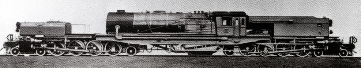 Builder's picture of no. 2298, c. 1938
 -
 Class GM at Braamfontein depot, c. 1940
 -
 Class GM with its Type X-17 water tender, c. 1940

.jpg)
.jpg)
References[edit]
- ^ a b c d e f g Holland, D. F. (1972). Steam Locomotives of the South African Railways. Vol. 2: 1910-1955 (1st ed.). Newton Abbott, England: David & Charles. pp. 96–97. ISBN 978-0-7153-5427-8.
- ^ a b c d e f g h i j k l m Espitalier, T.J.; Day, W.A.J. (1946). The Locomotive in South Africa - A Brief History of Railway Development. Chapter VII - South African Railways (Continued). South African Railways and Harbours Magazine, November 1946. pp. 894-896.
- ^ a b c d e f g Paxton, Leith; Bourne, David (1985). Locomotives of the South African Railways (1st ed.). Cape Town: Struik. pp. 94–95. ISBN 0869772112.
- ^ a b c d e f g h Durrant, AE (1989). Twilight of South African Steam (1st ed.). Newton Abbott: David & Charles. p. 114. ISBN 0715386387.
- ^ a b c d e f g h i j Durrant, A.E. (1981). Garratt Locomotives of the World. David & Charles. pp. 129-130. ISBN 0-7153-7641-1.
- ^ a b c Soul of A Railway, System 7, Western Transvaal, based in Johannesburg, Part 24: Krugersdorp-Zeerust-Mafeking (Home Signal), Part 1 by Les Pivnic. Introduction: Engine Power, Caption 5. (Accessed on 5 May 2017)
- ^ Hamilton, Gavin N., The Garratt Locomotive - Garratt Locomotives produced by Beyer, Peacock, retrieved 10 November 2012
- ^ South African Railways & Harbours/Suid Afrikaanse Spoorweë en Hawens (15 Aug 1941). Locomotive Diagram Book/Lokomotiefdiagramboek, 2'0" & 3'6" Gauge/Spoorwydte, Steam Locomotives/Stoomlokomotiewe. SAR/SAS Mechanical Department/Werktuigkundige Dept. Drawing Office/Tekenkantoor, Pretoria. pp. VIII, 6a-7a, 33.
- ^ Soul of A Railway, System 7, Western Transvaal, based in Johannesburg, Part 22: Braamfontein by Les Pivnic: Braamfontein Yard, Loco, ERS and Old Kazerne Goods Yard, Part 1. Introduction, Caption 19, 48, 69. (Accessed on 4 May 2017)
- ^ Soul of A Railway, System 7, Western Transvaal, based in Johannesburg, Part 25: Krugersdorp-Zeerust-Mafeking (Home Signal), Part 2 by Les Pivnic. Captions 20, 21, 22. (Accessed on 6 May 2017)
- ^ Soul of A Railway, System 7, Western Transvaal, based in Johannesburg, Part 4. Johannesburg to Germiston by Les Pivnic. Caption 22. (Accessed on 28 March 2017)